- v50 information can now be added to pages in the main namespace. v0.47 information can still be found in the DF2014 namespace. See here for more details on the new versioning policy.
- Use this page to report any issues related to the migration.
40d Talk:Fluid logic
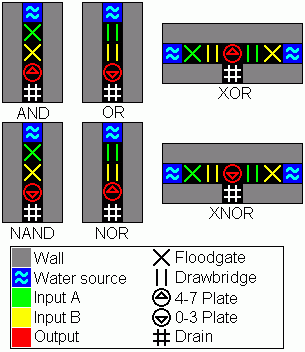
Can anyone explain how the XOR of the Mechanical-Fluid Gates work? I don´t seem to understand it...--Kami 17:34, 12 October 2009 (UTC)
- Sure. It assumes the pump is powered by a windmill on a map with strong wind (40 power). If neither input is on, the power is only transfered to the southeast gear assembly (total of 10 power consumed). If only the yellow gear assembly is connected (considered to be a logic high), then every gear assembly but the green input is powered (30 power in gear assys, 10 power for the pump). If only the green assembly is connected, the yellow assy and the white one to the north are both disconnected (25 power in gear assys, 10 for the pump). But if both assys are connected, the entire thing requires 45 power to work, and nothing turns. Easily modifiable with a huge number of gears for water wheel power. I believe a windmill farm would be necessary on a map with 20 or 10 wind. -Arrkhal 20:27, 12 October 2009 (UTC)
- Now I understand. But I think this should be mentioned anywhere. ^^
By the way, I don´t think this is a good concept. You´ll have to empower every single part of your "computer" by itself. And you´ll have to calculate your power well and build tons of useless gears. Complex logic will lead you to a state you can´t handle it anymore... I´ll think of it. --Kami 13:31, 13 October 2009 (UTC)- Probably not the best system, yeah. I was mainly just trying to think of a system which destroys a minimum amount of water, to be able to compute on a map with only murky pools. You may want to look at the mechanical logic page, too. That's where I got the XOR design from. If there's a better way to make an XOR with gears and axles, I can't think of it. -Arrkhal 23:36, 13 October 2009 (UTC)
- Just hook the inputs up to the same gear- gear assemblies toggle. You'll need to "invert" the pressure plate, though, since hooking up two levers to a gear assembly leaves them both off and the power on. With one lever pulled, the power's off, and with both it's back on. 23:34, 14 October 2009 (UTC)
- I think this is more mechanical computing than water computing, because in this case the logic lies within the gears and power. The water is only used to convert power into lever signals.
But I see the destruction of water is a problem you will have to solve if you have limited ressources. Did you ever consider to use hatches to control the flow of water? This would require more pumping, but could work?
An XOR with gears that is not based on underpovering can be made the same way you did for the infinite flow gates above. A XOR B = (A AND NOT B) OR (NOT A AND B) | A XNOR B = (A AND B) OR (NOT A and NOT B)
Oh, and here is an short example of computing I tested: http://mkv25.net/dfma/movie-1745-dwarfputerv01 --Kami 10:46, 15 October 2009 (UTC)
- Probably not the best system, yeah. I was mainly just trying to think of a system which destroys a minimum amount of water, to be able to compute on a map with only murky pools. You may want to look at the mechanical logic page, too. That's where I got the XOR design from. If there's a better way to make an XOR with gears and axles, I can't think of it. -Arrkhal 23:36, 13 October 2009 (UTC)
- Now I understand. But I think this should be mentioned anywhere. ^^
Help: Time Keeping, a counting problem[edit]
Ok, I am well-and-truly crazy, but I want to make a DF clock. One which accurately tracks days and month. (Additional awesome for tracking 'hours' within days, but that would be crazy). So, i think i know what to do conceptually, but i'm having problems making the leap from concept to a concept of execution in the game. (Part of this certainly results from my having had problems getting pressure plates to work properly before)
Thoughts:
So, there's going to be some minimal repeater, which toggles with a frequency of f. Each toggle of the repeater fills a 1x1 area with 7/7 water, or dumps that water.
The resevoir into which the water is dumped with each toggle is 7x1, causing it to fill to 1/7 everywhere the first time, 2/7 the second, etc... When it reaches 7/7 it dumps...
...into a 7x7, which similarly fills up to 7/7 over 7 dumps of the second level system.
Issues: How do i ensure perfect draining of a 1x7 area in relatively short time? A 7x7 area? How many iterations / what final depth on last iteration do i need to count out a day/month? (Ie, how short or long does a repeater tend to run per repeat, and what multiple of that is sufficient to count out a month?)
Biggest issue: It must work slowly enough to allow draining yet quickly enough to permit accurate counting of days.
I suppose after the 1x7 it could trigger another 1x1 repeater, and i could just parallelize that way, with each repeater being triggered slower and slower. The 7x1 could also be a 6x1 column with a 1x2 top layer (7 cubes, 6 vertical, 7th needs a floor to measure depth), which would help with rapid draining, but will it be rapid enough?
So, any thoughts? How can I build this and not go crazy?
--Squirrelloid 09:45, 31 October 2009 (UTC) has the potential to become the greatest dwarfputer ever!
Here are some suggestions:
- If you fill an area with 1/7 water you will encounter a problem with evaporation, especially when it takes more time until you add more water for example when you´re counting months.
- Possible solution: You could work with multiple of 2/7 water or use some system that adds an additional 1/7 water per field for the first time.
- You can´t totally drain an area, even it goes -1 z-level through a whole at one side a 1/7 portion of water will always stay there. One possibility would be to use a hatch or a bridge, but then you can´t use a pressure plate as trigger.
- Imagination: 6/7 would be perfect if you have an 1x3 area and want to use multiple of 2/7 water.
- Don´t use larger areas for each level like you suggested (1 7 43 ...). Use multiple small components connected via pressure plate in a row.
- Suggest to work with components like others used for their alculation machines. Using the height of water is not the the best idea comparing to pure binary logic with filled/not filled.
- I think the best repeater would be a that goblin one.
--Kami 11:18, 31 October 2009 (UTC)
- Ok, big first issue: I made a rough build of a single component as i proposed, just to see if it would work at all. It doesn't. For some reason I can't have a single pressure plate open the floodgates *and* close the hatches? Am i misunderstanding something about the way pressure plates work?
- So, i'm filling with pressurized water, meaning the 1x1 component goes to 7/7 instantaneously. This means it should open the floodgate to drain the 1x1 and close the hatch to prevent additional fill of the 1x1 at the same time. Flood gate opens fine but the hatch refuses to close... What the heck am i doing wrong? Shouldn't the pressure plate toggle both hatches and floodgates to the opposite of their current positions?
- If it toggles multiple times, maybe i could just open and close components with a 3/7-4/7 signal and it could just repeatedly toggle the components at some frequency that could be counted with other components... of course, then i need to time every component separately - now that sounds like a nightmare.
- This would be easier if screw pumps didn't create water, so their supply was actually limited by how much had gone in...
- Issue with lots of binary components - that sounds a lot more space intensive. It does, however, sound more foolproof.
- --Squirrelloid 13:00, 31 October 2009 (UTC)
- Relevant additional question - Does anyone know how many 'steps' there are in a DF day? Month? Year? --Squirrelloid 13:19, 31 October 2009 (UTC)
- Your Problem is: pressure plates and levers have a "on" and a "off" state. "On" opens door, floodgates and hatches, "off" closes them. It is not possible to open one thing and close another directly with the same lever or pressure plate. Look at lever for more information. You´ll have to use some kind of signal-inverter or use a bridge to block flow. Bridges can be used as inverted doors (fluid logic). --Kami 15:00, 31 October 2009 (UTC)
- That's really stupid. But creatures stepping on a pressure plate just work like a toggle? What the hell? Why can't fluids work more like that. --Squirrelloid 17:02, 31 October 2009 (UTC)
Ok, I think I have a design that might work. Its not exactly binary, but its going to be a whole lot easier to build rather than figuring out the mess of logic.
So the example repeater on the Repeater page says it works ~1/300 'steps'. Assume there are 1200 'steps' in a day.
P|_+_|_+^_
Where P is pressurized water, | is a floodgate, + is a drawbridge, ^ is a 3/7-7/7 pressure plate, and _ is a hatch. The doors and bridges are linked to the pressure plate in the repeater, which alternately toggles them, so it counts up to 4. The ^ at the end opens all the hatches when 'on' (voiding the system), and also triggers a day counter, built on similar principles but 28 long. The day counter similarly triggers a month counter that is 12 long. The difference being each step of the day/month counter needs a ^ to trigger a display somewhere (unless you use the counter itself as the display, which is admittedly inelegant).
... The ^ from the repeater is going to toggle on and off once per iteration isn't it, so it'll do two parts instead of one per 300 'steps'? crap. I suppose you need to make it twice as long then, huh? Ie:
P|_+_|_+_|_+_|_+^_
(As much fun as building a full binary system would be, I want something that can be constructed relatively quickly, which in this case means 'with a limited number of logic structures')
--Squirrelloid 08:44, 1 November 2009 (UTC)
- Ok, it doesn't work, i can't keep water at 7/7 through the whole thing (annoying).
- a day is also not an integer multiple of that particular repeater. Its somewhere between 3 and 4 iterations. Ugg, getting this to work properly is going to drive me nuts. I'm not really sure I want to try to code in binary... --Squirrelloid 12:04, 1 November 2009 (UTC)
- Hmm.. with a little more complication i don't need to have them in sequence. But drainage becomes a bigger engineering problem... Ok, lets solve the repeater:day ratio problem first, then i'll try to figure out how to 'wire' this mess. --Squirrelloid 12:39, 1 November 2009 (UTC)
- I have seen a video of a goblin running forth an back towards triggered doors. http://mkv25.net/dfma/movie-1299-goblininfiniteloop I think this would be a perfect and scalable repeater... I think if you know how fast a goblin can run and how long it would take to find the new way, you´ll be able to have him "repeat" exactly x times a day. --Kami 19:39, 2 November 2009 (UTC)
- So, there's this theory that a day has 1200 'ticks'. Bridges and floodgates have a 100 tick delay (assuming they're built *before* the pressure plate, o/w 101 ticks...). Theory seems to suggest pressurized water pushes 7/7 water into an open space each tick. So the minimal repeater with pressurized water: P+^| has a 202 tick cycle (assuming +,| are built before ^). Theory - we need to extend the front end of this 38 squares to get a 240 tick repeater (1200/240 = 5).
- by front end i mean something like P+____..._____+^|, where _ are open space with hatch covers, because this needs to completely drain each cycle, and also not interfere with the spacing of the actual repeater, just the time it takes to refill/retrigger.
- I need to actually build this and run some timing tests... The other problem is i'm assuming infinitely pressurized water - need to check feasibility if i'm draining 38 squares of water each cycle of the repeater... (admittedly, i can use its waste water to pressurize whatever adder i have keeping track of how often its repeated...)
- --Squirrelloid 20:17, 2 November 2009 (UTC)
Image improvement[edit]
HebaruSan, you added an 'Image Rules Notice'. Can you explain what you'd like to have improved? Using the default tileset would rather reduce than improve clarity.
- The only thing that's rule-related is to convert from GIF to PNG, which is minor. I'd still find these a bit confusing after that, though; a few suggestions:
- Change |thumb to |right or |left so they appear at full size, since they're an important part of the content and not an aside.
- Omit the gridlines.
- Use a black background.
- Use the foreground color for color-coding the functional pieces. So the gear assembly itself would be green or purple, not the tile under it.
- Use a thicker/bolder font.
- Maybe draw some partially transparent arrows over the tiles to illustrate the flow of the logic. I.e., from this tile, to that tile, to that tile, ...
- Maybe split them out into one graphic per diagram. This may not matter much once they're full-size, though.
- I found User:Hussell/SetResetLatch to be pretty readable, using mostly the standard tileset. I'll try to find some time today to mock one of these up with RT, to see how it looks.
- --HebaruSan 14:03, 9 November 2009 (UTC)
- With the sole exception of screwpumps, i think the default tileset would make things a lot clearer. Also, why say 'input' and 'output' when what you mean is 'water' and 'pressure plate'? A less formal abstract treatment and a more DF-termed treatment might make it more accessible. --Squirrelloid 14:36, 9 November 2009 (UTC)
- I allready tried to use default tileset, not for water logic but for mechanical logic, and failed so far. Especially pumps and plates for different levels are a problem, but also linkage issues and I/O can be difficult do display. But I have to admit that Hussell's SetResetLatch looks quite good.
@Squirrelloid: I don't think the problem of this page are the images. There should be more Text to explain how they are working.--Kami 15:11, 9 November 2009 (UTC)- For comparison, here's what it might look like with black backgrounds, varying foregrounds, no gridlines, and thicker glyphs:
- --HebaruSan 17:29, 9 November 2009 (UTC)
- I allready tried to use default tileset, not for water logic but for mechanical logic, and failed so far. Especially pumps and plates for different levels are a problem, but also linkage issues and I/O can be difficult do display. But I have to admit that Hussell's SetResetLatch looks quite good.
- With the sole exception of screwpumps, i think the default tileset would make things a lot clearer. Also, why say 'input' and 'output' when what you mean is 'water' and 'pressure plate'? A less formal abstract treatment and a more DF-termed treatment might make it more accessible. --Squirrelloid 14:36, 9 November 2009 (UTC)

CMOS logic[edit]
The logic gate described as CMOS logic is actually classic transistor logic, which relies on the flow of current (water). The point of CMOS logic is that there is only flow at state changes. It would look like this in Dwrf Fortress (not tested yet):
║S║ - water source
╠X╣ - floodgate
║p║ - pressure plate
╠B╣ - drawbridge
║D║ - drain
The floodgate and the bridge are connected to the same input, and the pressure plate will be the output (either positive or negative). It has an advantage of low water usage (the same as real CMOS circuits), so it can be connected to a permanent water source (or even a pond that is filled occasionally), and can be drained by letting the water into a large cavern where it will evaporate.
89.132.124.161 13:11, 17 November 2009 (UTC)
- I'm on to testing this logic and will write to the main page when ready. Petersohn 07:50, 18 November 2009 (UTC)
- Done. Petersohn 12:46, 30 November 2009 (UTC)
- I have added my personal work on this subject to my user page. The gates I use are similar, but I feel they may yet contribute. Gammon 00:45, 1 December 2009 (UTC)