- v50 information can now be added to pages in the main namespace. v0.47 information can still be found in the DF2014 namespace. See here for more details on the new versioning policy.
- Use this page to report any issues related to the migration.
Difference between revisions of "40d:Fluid logic"
m |
m (Started revision (working in progress) / see hidden comment) |
||
| Line 4: | Line 4: | ||
[[File:Logic1.gif|thumb]] | [[File:Logic1.gif|thumb]] | ||
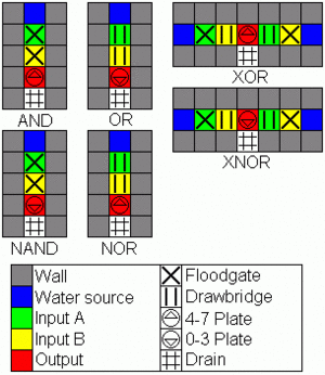
These logic gates are relatively simple and cheap to make, but require an infinite amount of water and infinite drainage to operate (alternatively a power-hungry pump-circuit). Credit goes to numerous forum members for refining these designs.<br clear="all"/> | These logic gates are relatively simple and cheap to make, but require an infinite amount of water and infinite drainage to operate (alternatively a power-hungry pump-circuit). Credit goes to numerous forum members for refining these designs.<br clear="all"/> | ||
| + | |||
| + | <!-- //Working in progress | ||
| + | <div style="position:relative; float:none;"> | ||
| + | '''(N)AND''' | ||
| + | {| cellpadding="0" cellspacing="0" style="border-spacing:0; border-style:solid; border-width:thin; border-color:#000000;" | ||
| + | | | ||
| + | {| cellpadding="0" cellspacing="0" style="border-spacing:0; padding:0; margin:0; vertical-align:middle;" | ||
| + | |- | ||
| + | |{{RTL|#222}} | ||
| + | |{{RTL|#222}} | ||
| + | |{{RTL|#222}} | ||
| + | |{{RTL|#222}} | ||
| + | |{{RTL|#222}} | ||
| + | |- | ||
| + | |{{RTL|#00A|≈|#DDD}} | ||
| + | |{{RTL|#AAA|X|#444}} | ||
| + | |{{RTL|#AAA|X|#444}} | ||
| + | |{{RTL|#00A|^|#DDD}} | ||
| + | |{{RTL|#222|·|#BBB}} | ||
| + | |- | ||
| + | |{{RTL|#222}} | ||
| + | |{{RTL|#222}} | ||
| + | |{{RTL|#222}} | ||
| + | |{{RTL|#222}} | ||
| + | |{{RTL|#222}} | ||
| + | |} | ||
| + | |} | ||
| + | </div> | ||
| + | An AND gate is simply created by putting two floodgates in a row, each one connected to one of the input triggers. When both floodgates recieve an on signal, they will open and let the water pass (coming from an unlimited source left in the diagramm). The pressure plate behind the floodgates has to be constructed to react on 4-7 water. If you use a pressure plate reacting on 0-3 water, you'll get a NAND gate instead. It's also possible to add more floodgates to process more than two signals in a conjunction, and to use two oppositional pressure plates to get the result of the AND and NAND operation at the same time.--> | ||
==Mechanical-Fluid Gates== | ==Mechanical-Fluid Gates== | ||
Revision as of 16:33, 17 December 2009
Fluid logic is a form of computing which uses a fluid (generally water) controlled by various means, to trigger pressure plates and hopefully accomplish some desirable result.
Infinite Flow Gates
These logic gates are relatively simple and cheap to make, but require an infinite amount of water and infinite drainage to operate (alternatively a power-hungry pump-circuit). Credit goes to numerous forum members for refining these designs.
Mechanical-Fluid Gates
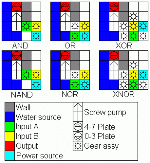
The water sources in these diagrams are located 1 z-level below the pumps and gear assemblies.
These gate designs have the advantage of destroying no water and requiring no drainage off the map, making them suitable for maps where infinite water and/or drainage may be a problem. The only fluid lost will be to evaporation. However, there are a number of disadvantages. They require significantly more materials and time to make, they require power, and a flood could have disasterous consequences, as it would cover all the plates at once.
For the XOR-Gate it is assumed that the gear is powered by a windmill on a map with strong wind (40 power). If both gears are active the XOR-Gate would need more than 40 power and will stop working. If you use a different source of power - a waterwheel with axles or combined windmills 20 power each - you´ll have to add or remove some gears or axles to calibrate it.
CMOS Transmission Gate and Inverter Logic
Perhaps the closest to utilizing water as a stand-in for electricity, transmission gate logic can be accomplished by simply having an infinite water source in place of all +Vs, and infinite drainage for all grounds. Simple floodgates behave as standard transmission gates, while bridges are inverted gates. However, unlike the other forms of fluid logic, but like a real world electrical circuit, a dedicated inverter is required, which must be hooked up to +V and ground.
Advanced CMOS Gates
This type of logic uses the same concept as real CMOS circuits do, which causes them to minimalize power (in this case, water) consumption. The idea is that water should only flow when there is a state change.
Basic Design
Let's say we want to evaluate the logical expression f. It can be a simple and or or gate, or anything more complicated. Follow the following scheme:
≈
|
≈
|
≈
|
╗
|
A
|
╔
|
║
|
^
|
║
|
║
|
B
|
║
|
║
|
#
|
║
|
Here, A is a set of floodgates and/or drawbridges that let water flow exactly when f evaluates to true, B is the same except that it lets water flow when f evaluates to false, ^ is a pressure plate set to activate on water levels 4-7, and # is the drain.
Examples
In the following examples, X is a floodgate, and ╬ is a drawbridge. Red ones are connected to input A, green ones to input B and blue ones to input C.
NOT
≈
|
≈
|
≈
|
╗
|
╬
|
╔
|
║
|
^
|
║
|
║
|
X
|
║
|
║
|
#
|
║
|
AND
≈
|
≈
|
≈
|
≈
|
╗
|
X
|
╔
|
═
|
║
|
X
|
║
|
█
|
║
|
^
|
╚
|
╗
|
║
|
█
|
█
|
║
|
║
|
╬
|
╬
|
║
|
║
|
#
|
#
|
║
|
OR
≈
|
≈
|
≈
|
≈
|
╗
|
X
|
X
|
╔
|
║
|
█
|
█
|
║
|
║
|
^
|
╔
|
╝
|
║
|
╬
|
║
|
█
|
║
|
╬
|
║
|
█
|
║
|
#
|
║
|
█
|
XOR
This is not as straightforward as the previous ones. The true expression is the following: (A and not B) or (not A and B). The false expression: (A and B) or (not A and not B).
So the gates look like the following:
≈
|
≈
|
≈
|
≈
|
≈
|
╗
|
X
|
║
|
X
|
╔
|
║
|
╬
|
║
|
╬
|
║
|
║
|
█
|
^
|
█
|
║
|
║
|
╬
|
║
|
X
|
║
|
║
|
╬
|
║
|
X
|
║
|
║
|
#
|
║
|
#
|
║
|
Advantages And Disadvantages
The basic advantage of this design is that it uses much less water than infinite flow gates. A river is enough to supply even the more complex systems, maybe with an added reservoir to neutralise flow irregularities. Similarly, for the drain, it is enough to excavate a cavern where the water can evaporate.
The disadvantage is that it requires much more resources and time to construct, especially more mechanisms. And more planning, since floodgates tend to block paths when constructed.
Faster Version
The main factors that affect the speed of these gates are the delays of floodgates and bridges, and the switch-off delay of pressure plates. These cannot be eliminated.
Another factor is the flowing speed of the water. It can be improved. First, the water should flow in from a reservoir a few z-levels higher then the gates themselves (the more the better). This way, water will flow in much faster. Next, replace the pressure plates with up stairs, and make a 2x1 room one z-level above. On on tile is a down stair, and on the other is the pressure plate. Now the water will also flow out faster, or at least the pressure plate will switch off sooner.
This increases the water consumption a bit, but it still remains relatively low.


