- v50 information can now be added to pages in the main namespace. v0.47 information can still be found in the DF2014 namespace. See here for more details on the new versioning policy.
- Use this page to report any issues related to the migration.
Difference between revisions of "User:Gammon"
| Line 118: | Line 118: | ||
P O.1 PR.PL. 6/7 | P O.1 PR.PL. 6/7 | ||
</pre> | </pre> | ||
| − | [[File: | + | [[File:Fig4XAND2.png]][[File:Fig4XAND1.png]][[File:Fig4XAND0.png]] |
Revision as of 18:12, 1 December 2009
Fluid logic
Disclaimer: This is my personal work on the topic, and felt inclined to share it after reading about the same topic on DF Wiki. Use this information for your own works on the matter.
Fluid logic is a form of computing which uses a fluid (generally water) controlled by various means, to trigger pressure plates and hopefully accomplish some desirable result.
Key
Floodgate
X FLOOD ALLOW FLOW WHEN ON
Large Raising Bridge
[  Start      CH.BR.   ALLOW DRAIN WHEN ON, ALLOW FLOW WHEN OFF
]  End
Note: Channel below the end piece.
Small Raising Bridge
[ BRIDGE ALLOW DRAIN WHEN OFF
Note: Channel above piece.
Pressure Plate
P             PR.PL.   X/X ON
P<                     ON UNDER MAXIMUM
>P                     ON OVER MINIMUM
Channel
. DRAIN.
Note: Also used as a drain bypass to route around objects.
Source
~ WATER SOURCE.
Note: Only depicted in XAND and XOR.
Notes
- Water source is above first input piece.
- -2, -1, 0 Refers to level.
- I is INPUT, O is OUTPUT. Numbered.
Gates
AND
    -1   0
     .   X    I.1  FLOOD
     [   .    I.1  BRIDGE
     .   X    I.2  FLOOD
     [   .    I.2  BRIDGE
         P    O.1  PR.PL. 6/7
OR
         0
         [    I.1  BRIDGE
         ]         CH.BR.
         [    I.2  BRIDGE
         ]         CH.BR.
         P    O.1  PR.PL. 0/5
NOT, INVERTER
         0
         [    I.1  BRIDGE
         ]         CH.BR.
         P    O.1  PR.PL. 6/7
NAND
    -1   0
     .   X    I.1  FLOOD
     [   .    I.1  BRIDGE
     .   X    I.2  FLOOD
     [   .    I.2  BRIDGE
         P    O.1  PR.PL. 0/5
NOR
         0
         [    I.1  BRIDGE
         ]         CH.BR
         [    I.2  BRIDGE
         ]         CH.BR
         P    O.1  PR.PL. 6/7
XOR
-2  -1   0
     ~   ~
 .   X   [    I.2  FLOOD      I.1  CH.BR.
 [   .   ]    I.2  BRIDGE
 .   X   [    I.1  FLOOD      I.2  CH.BR.
 [   .   ]    I.1  BRIDGE
         P    O.1  PR.PL. 0/5
XAND
-2  -1   0
     ~   ~
 .   X   [    I.2  FLOOD      I.1  CH.BR.
 [   .   ]    I.2  BRIDGE
 .   X   [    I.1  FLOOD      I.2  CH.BR.
 [   .   ]    I.1  BRIDGE
         P    O.1  PR.PL. 6/7
Computing
Latch
In Dwarf Fortress, a latch is a circuit which has two stable states and thereby can store one bit of information.
A circuit incorporating latches has state; its output may depend not only on its current input, but also on its previous inputs.
S/R Latch
     0   0
     [   [    I.S   I.R
     ]   ]
     [   [    I.Q   I.Q
     ]   ]
    <P  <P    O.Q   O.Q
Note: Use a Signal Trap when attempting to capture creature plate signals. Hold RESET while system boots.
Signal Trap
    -1   0   1
     X   .   X   I.R     I.S
        <P           O.Q
Notes
- INPUT S to SET, INPUT R to RESET
- Uses a door and hatch. Useful for capturing creature plate OUTPUT.
Clock Signal
         0
         [   IC  CH.BR.
         ]
        <P   OC  PR.PL.
Note: ACCURACY UNTESTED.
Methods Of Implementation
The computational "house" is a collection of gates and purpose-made components for the computation of inputs and harvesting of results.
A source of water is pumped into a reservoir with the computational devices arranged below it to accept the water. Below these devices is a system for carrying away the used water.
The system must be able to carry the water at an adequate rate. Pumps are one way to assure this: they take the water to a river or map edge. Untested is the method of "atom-smashing" the water; it would greatly minimize the work needed, and indeed this already occurs inside the devices.
Of concern is what is known as "sloshing": where water can cause effect upon a pressure plate more then once per operation. This can cause chaos in the computer and completely ruin it. Pressure must be kept as high as possible; and drainage faster then the rate which pressure introduces water into the computer.
Reservoir
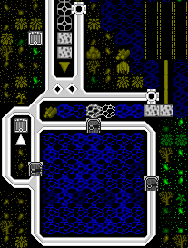
A pump can be seen supplying water to the reservoir from a brook. The door above determines whether the reservoir may fill. Underneath the water are a series of hatches over the computer components, determining whether the computer is on or off. To the left is a protected access shaft. The pump at the topmost is the highest in a series of pumps, reaching below to remove waste water.
Computer Components
Here can be seen an S/R Latch: where two NOR gates have their outputs crossed to the others second input. This allows 1 bit to be stored.
An access shaft, I, and a door, X, allow workers to reach the site.
EDIT LATER
Drainage
Here a pump, %, can be seen removing water from a pit below the S/R Latch. There is ample conduit to bring the water to the brook and pump into it. A waterwheel, gear assembly, and two axles bring power to the pumps.
EDIT LATER
