- v50 information can now be added to pages in the main namespace. v0.47 information can still be found in the DF2014 namespace. See here for more details on the new versioning policy.
- Use this page to report any issues related to the migration.
Difference between revisions of "User:Larix/MPL/3"
| Line 68: | Line 68: | ||
[[File:DieUhr2.png]] | [[File:DieUhr2.png]] | ||
| − | There's a medium-friction track stop on each connection track, the final tile, under the | + | There's a medium-friction track stop on each connection track, the final tile, under the pressure plate, is a corner sending the cart onto the "backwards" ramp of the partnered derailer. This results in the cart being so fast on entry that it derails over the ramp pit, slams into the wall and falls down onto the "forward" ramp. This greatly increases the time required to build up to derail speed, giving a full return time of 720 steps for each repeater. I started three of these repeaters 240 steps apart, so every 240 steps one "full round" signal is received and can be counted, five of them add up to a full day. |
Revision as of 17:14, 11 December 2013
Dedicated devices
As with other alternative logic disciplines, MPL is in many ways inferior to mechanical logic when it comes to the actual logic gates. Mechanical logic performs nearly instantaneously and requires little space. It's also a lot easier to run multiple mechanical operations off a single switch by running power through "master gears", while in MPL you have to individually connect every single device to every desired signal source. Mechanical logic, however, is not capable of generating signals by itself, of lasting data storage and incrementation ("counting") - the only "output" of mechanical logic is transfer of power and all states of mechanisms directly reflect the state of inputs, they cannot hold a "memory state" while input changes. Alternative logic types are required to generate and store signals. For counting, for repeating signals and to implement "memory", your options are fluids and minecarts, and MPL is an attractive choice here, because it's naturally liquid-less and can be implemented without use of power.
This is only a selection of MPL circuits i've built. They're mostly custom-made on the spot when i had the need for a circuit to perform a specific operation.
Counter
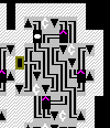
For speed regulation and cart management, there are a bump wall and bunker pit to the east. The operational unit is the angled three-pit ramp in the middle. The ramps are engraved with track like this:
   ║
  =╠
When the hatch cover is open, a cart coming from the west will pass through to the east, one from the north will pass through to the south. If the hatch cover is closed, a cart coming either from the west or from the north will exit to the north. Thus, the procession of operation when counting is:
1. cart enters the circuit on the outer ring, entering the three-ramp pit from the west.
2. as long as the hatch cover remains open, the cart will pass the ramp West->East, gets regulated by the bunker pit and remains circling around the outer ring.
3. once the hatch cover closes, the cart is diverted to the north and starts bouncing between the bump wall and the closed hatch cover.
4. once the hatch cover opens again, the cart passes through the pit to the south and leaves the counter circuit, e.g. entering the next one in the line.
A series of such counters, arranged in a circle, can be operated from a single input signal connected to all hatch covers and will thus count how often this input has cycled. The reaction time to a changed signal is fairly long, up to 50 steps, so the input shouldn't cycle too quickly, or signals will get missed.
It is easy enough to glue two of these counters together and have a pressure plate on the connecting track, so it sends a signal of its own after every second advancement. This is in effect a binary counter, and combining several of these allows to perform binary addition and subtraction.
Luxury one-bit memory/counter
This is a binary counter cell which can add and subtract, and can also be set to one or zero. In the adder/subtractor design i came up with, the "memory" is the part which performs the actual calculations, directed by signals sent from another circuit "reading" the input. All carry calculations are done in the counter/result memory itself and additions are performed from highest to lowest bit.
The device consists of two counters, linked through a northern and a southern loop. When the central hatch cover in the cart's current half of the cell opens, it passes through the loop to the other half. If the hatch in the pit on the loop is open, the cart passes through without further effects, if the hatch is closed, the cart is sent on the "inner" branch of the switchover loop and touches a pressure plate which sends the carry (south sends negative/subtractive, north sends positive/additive carries) to the next higher bit. If both operative hatches are opened, the memory cell's status will change to the opposite; depending on further hatches opened or not, this may generate carries and work as addition or subtraction. If only one operative hatch is opened, together with the hatch in the resultant switchover loop, the cell's value is "set" to a specific value - if the cart was already on the desired side of the cell, nothing changes, obviously.
Bridge Repeater
A curiosity, a powerless repeater sending a signal every ~205 steps which can be used to operate a constantly opening and closing bridge. The only operational pit is the one to the north, a looped-ramp pit (ramps SW and NW) with the northern ramp covered with a hatch cover linked to the output plate. As long as the hatch cover is open, the cart will cycle through the pit and the flat half-circle directly west of it. Once the hatch closes - one hundred steps after the cart went over the pressure plate - the cart will pass over the hatch, bump into the wall and move incredibly slowly to the south, fall into the bunker pit, leave at a slightly more sustainable speed and touch the plate again.
Double-action switch
An "edge detector" or, more simply put, a device to convert lever pulls into single on-and-off signals. The cart starts out on the hatch to the west, over the eastern ramp of a bunker pit. Once the input signal turns on, both hatches open, the cart falls into the pit, cannot leave to the west and thus leaves to the east, across the pressure plate and starts circling through the loop to the east until the hatches close again, when the cart will return from the pit to the north, pass the pressure plate again and bump against the wall to the west, coming to rest on the starting hatch cover again.
Auto-derailer
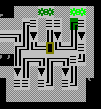
A device i used quite a lot in my first designs. The ramps are engraved with NW and SW track. The cart will cycle through the array, generally emerging on the northern track tile, cycling around to the south and entering the ramp again. It will keep accelerating until it becomes fast enough to derail. If there is open track to the north of the northern ramp on the level below, the cart will leave the array to the north at this point. Depending on the starting conditions, the cart can take anywhere from ten to 350 steps before leaving the derailer. If the cart is kept in the derailer, e.g. by blocking the exit path with a door, the cart will not accelerate notably beyond the original derail speed, it will just be kept within the array at derail-capable speed.
Clock-capable repeaters
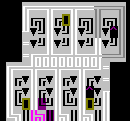
The visible ramp openings belong to looped pits, engraved SE-SW on the southern branch, NW-NE on the northern branch, with the second pit covered by the straight track leading out of the niches. The track stops on the exit points have high friction, the track stop just south of the northeastern ramp has low friction, all others medium friction. The return time is exactly 300 steps, 1/4 of a DF day. Collecting a single signal and plugging it into a four-step counter will give a full day.
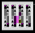
These are actually four repeaters, three of which are used to run a precise clock. Each repeater consists of two derailers, coupled like this below:
There's a medium-friction track stop on each connection track, the final tile, under the pressure plate, is a corner sending the cart onto the "backwards" ramp of the partnered derailer. This results in the cart being so fast on entry that it derails over the ramp pit, slams into the wall and falls down onto the "forward" ramp. This greatly increases the time required to build up to derail speed, giving a full return time of 720 steps for each repeater. I started three of these repeaters 240 steps apart, so every 240 steps one "full round" signal is received and can be counted, five of them add up to a full day.


